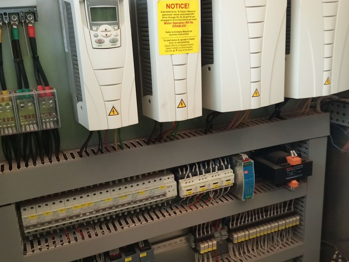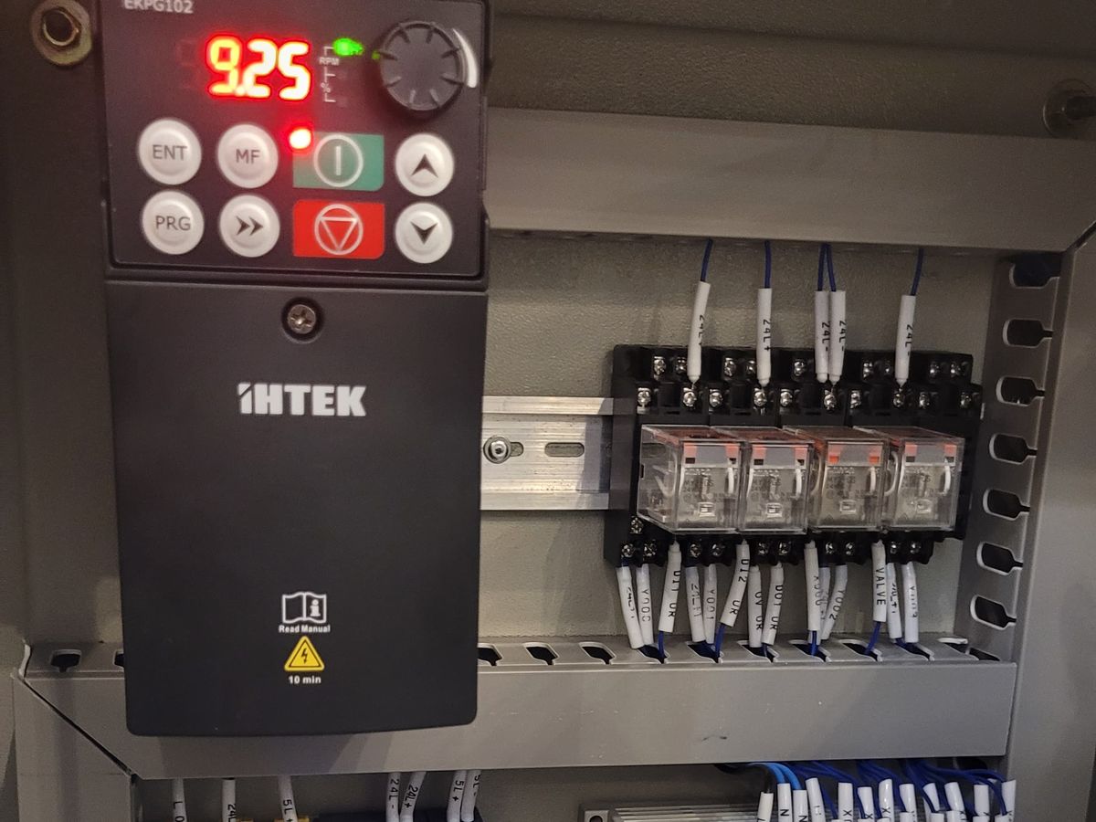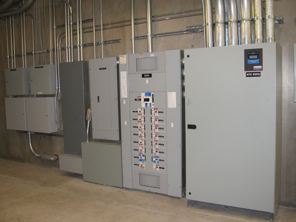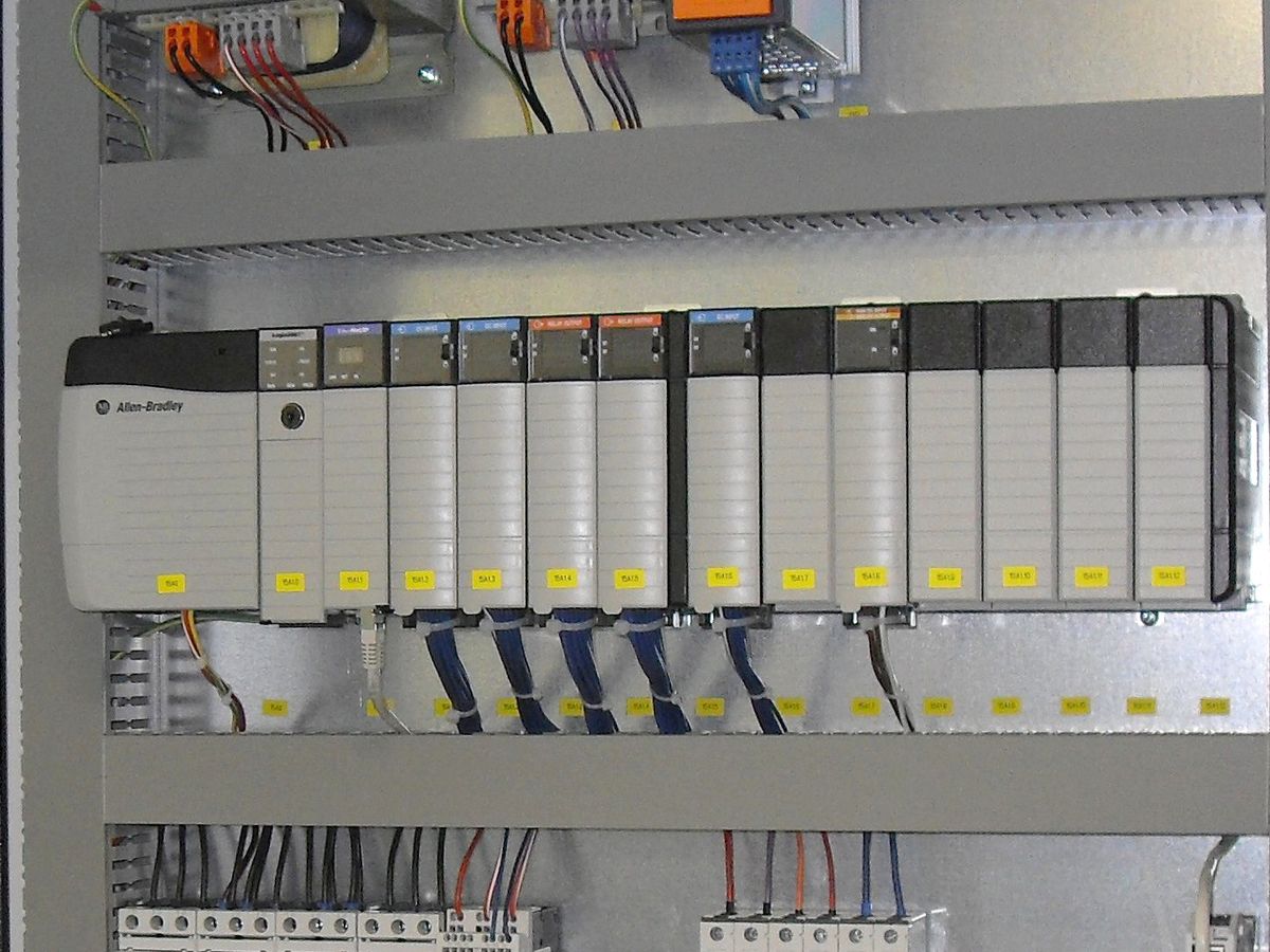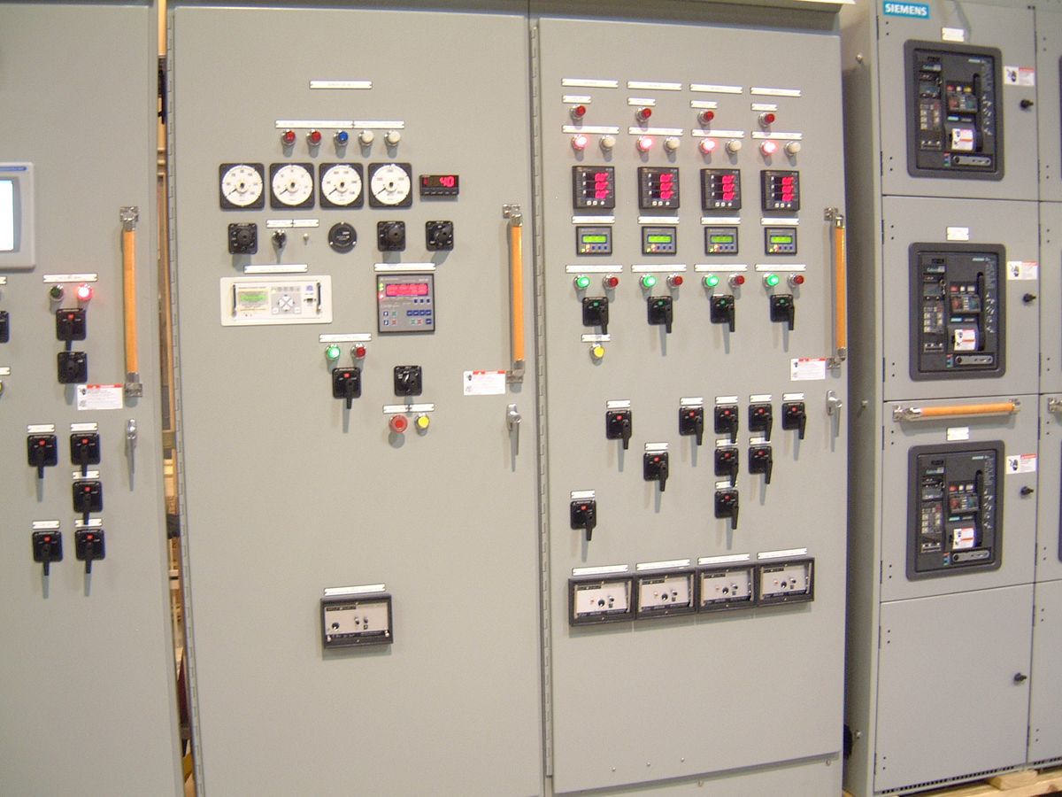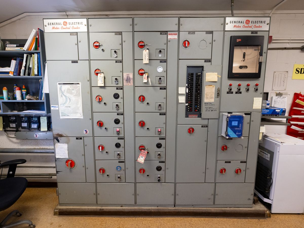
Control panels built to survive the field.
Every solution below is a standard we have built many times, with a drawing set and a factory test procedure behind it: PLC and RTU systems, enclosures, surge protection, solar power, backup power, measurement, racks and shelters, telecom and retrofits. Tell us which one is closest to your problem and we start from there.
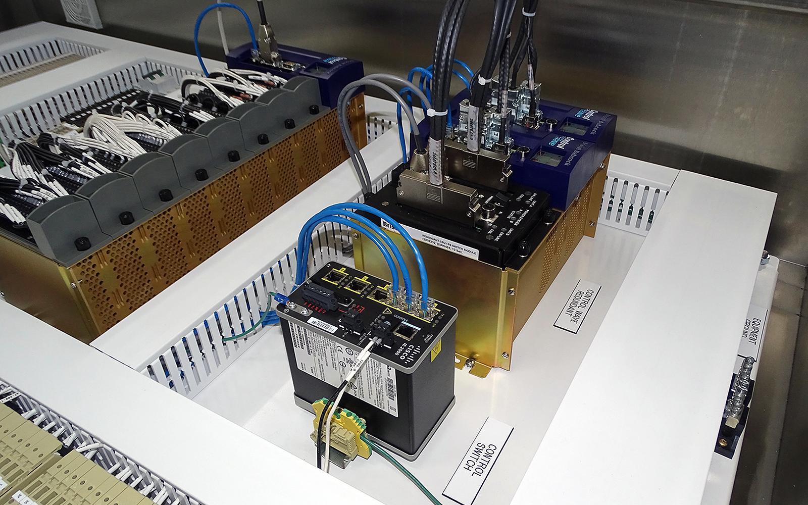 RTU panel · bench test before shipUL 508A
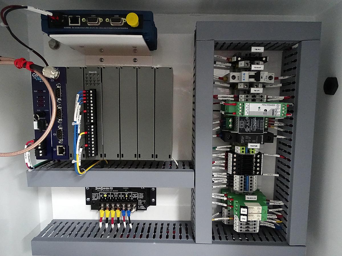
Reliable, accurate control for remote sites.
Remote monitoring, data collection, process control and telemetry. We build around ControlWave, Allen-Bradley and the platforms your standards specify, program and simulate on the bench, and document every point.
- RTU and flow computer panels
- PLC racks with local I/O
- Redundant controllers and managed Ethernet
- Modbus, DNP3 and serial integration
- Programming and simulation before ship
- As-built drawings in AutoCAD

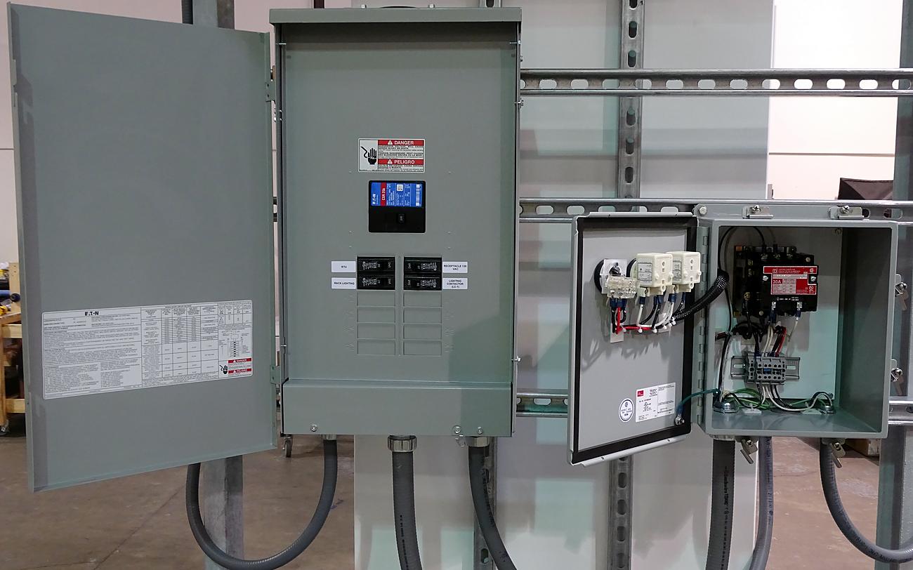
Laid out for the technician who has to work in it.
Clients come to us because we produce enclosures that meet and exceed the specification, on budget, with workmanship they can inspect at the factory acceptance test.
- NEMA 3R, 4, 4X and 12
- Painted steel, stainless and fiberglass
- Heating, cooling and ventilation sized to site
- Skid, pole and wall mount
- Segregated wire duct and marshalling
- Class I Division 2 where required
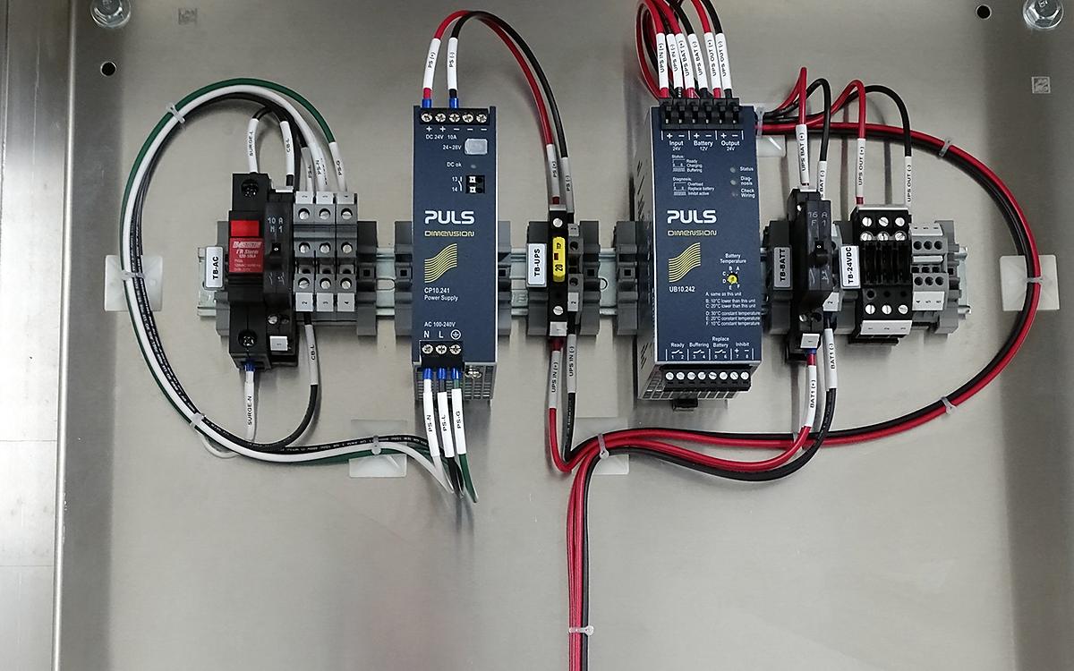
Rated under five nanoseconds. Proven after the storm.
Our systems have protected more than $100 million of equipment for major operators across the US, with SPDs rated under five nanoseconds response, and they keep working after the event that took out the neighbors.
- I/O, field instrument and 120 VAC protection
- Coordinated across power, signal and comms
- Grounding and bonding audits
- Site surveys after storm losses
- Written into a utility's installation standard
- PolyPhaser and Transtector partner products
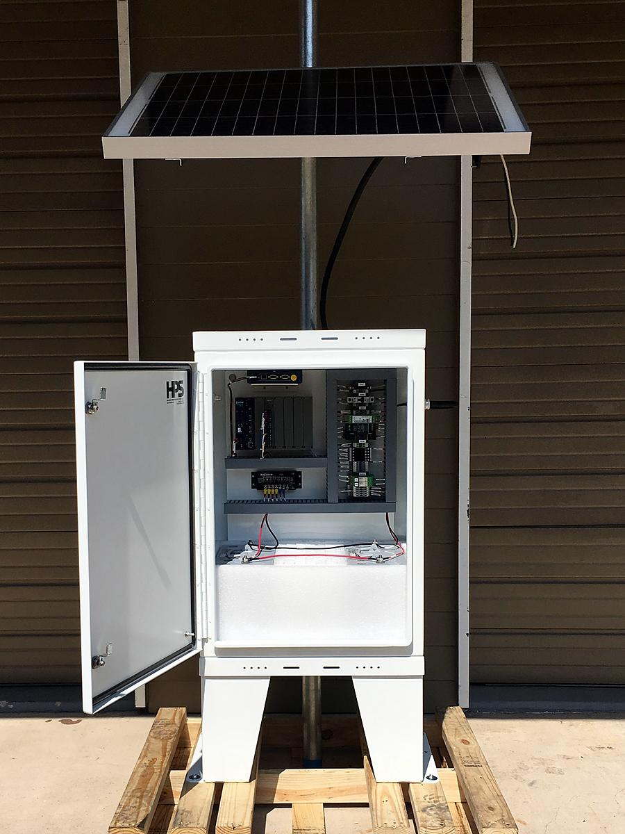
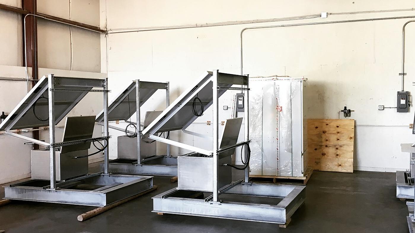
Reliable power where there is no utility.
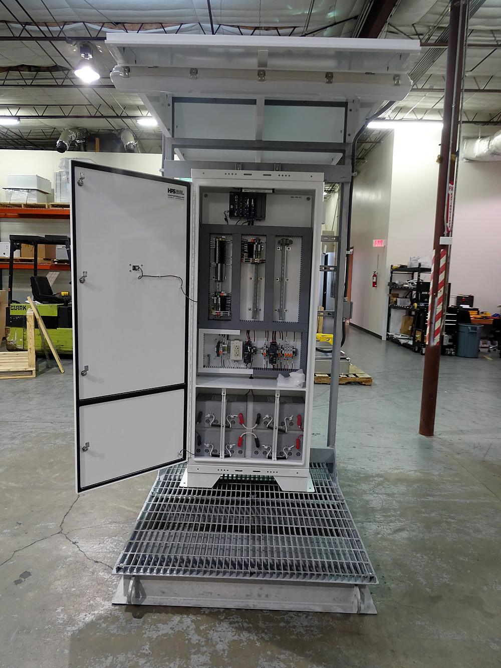
Complete passive power systems that prevent downtime and costly repairs at unpowered sites: array, charge controller, battery bank and protected DC distribution in one package.
- Sized to the worst month of sun, not the average
- Autonomy for the site's real load
- Temperature-compensated charging
- Surge protection on the PV input
- Skid or pole mount
- Cold-rated batteries and heaters
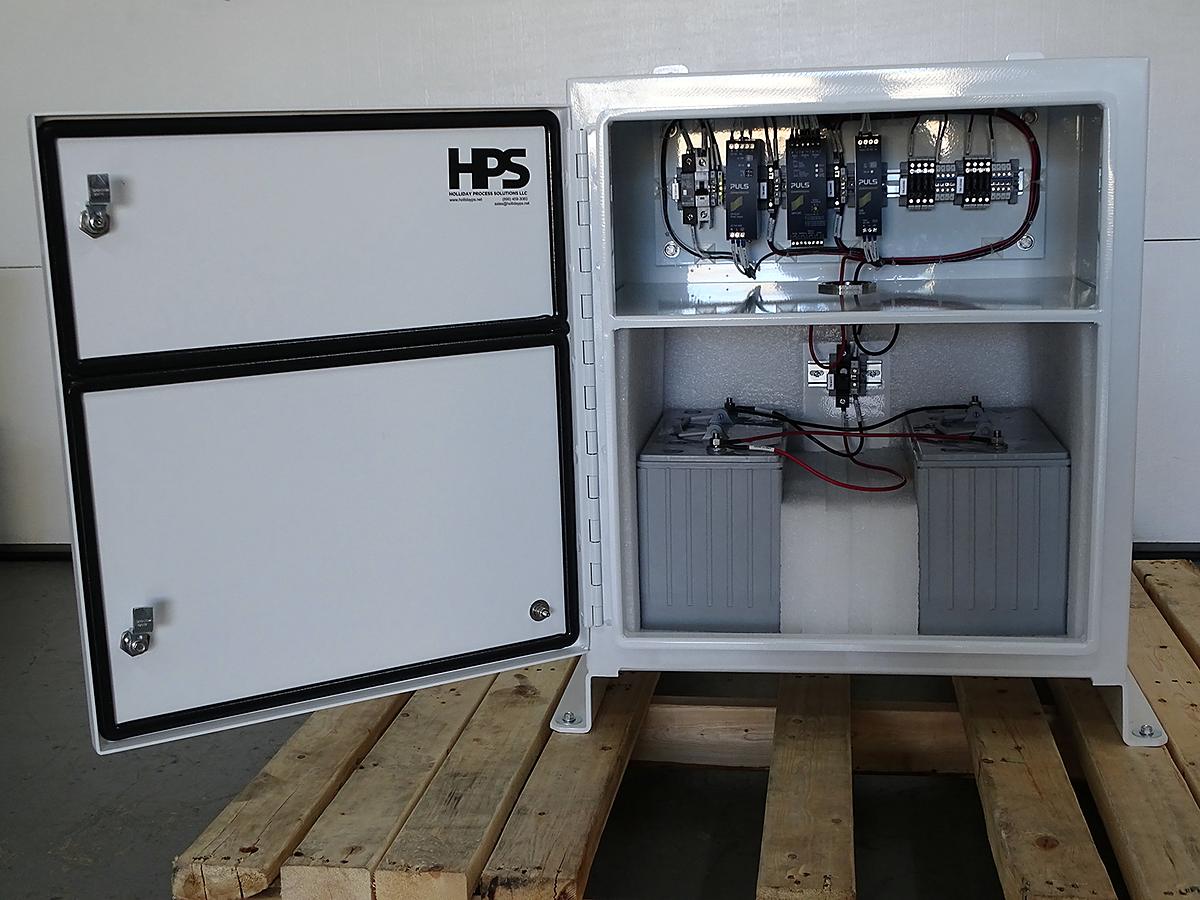
When the power is down, the site is up.
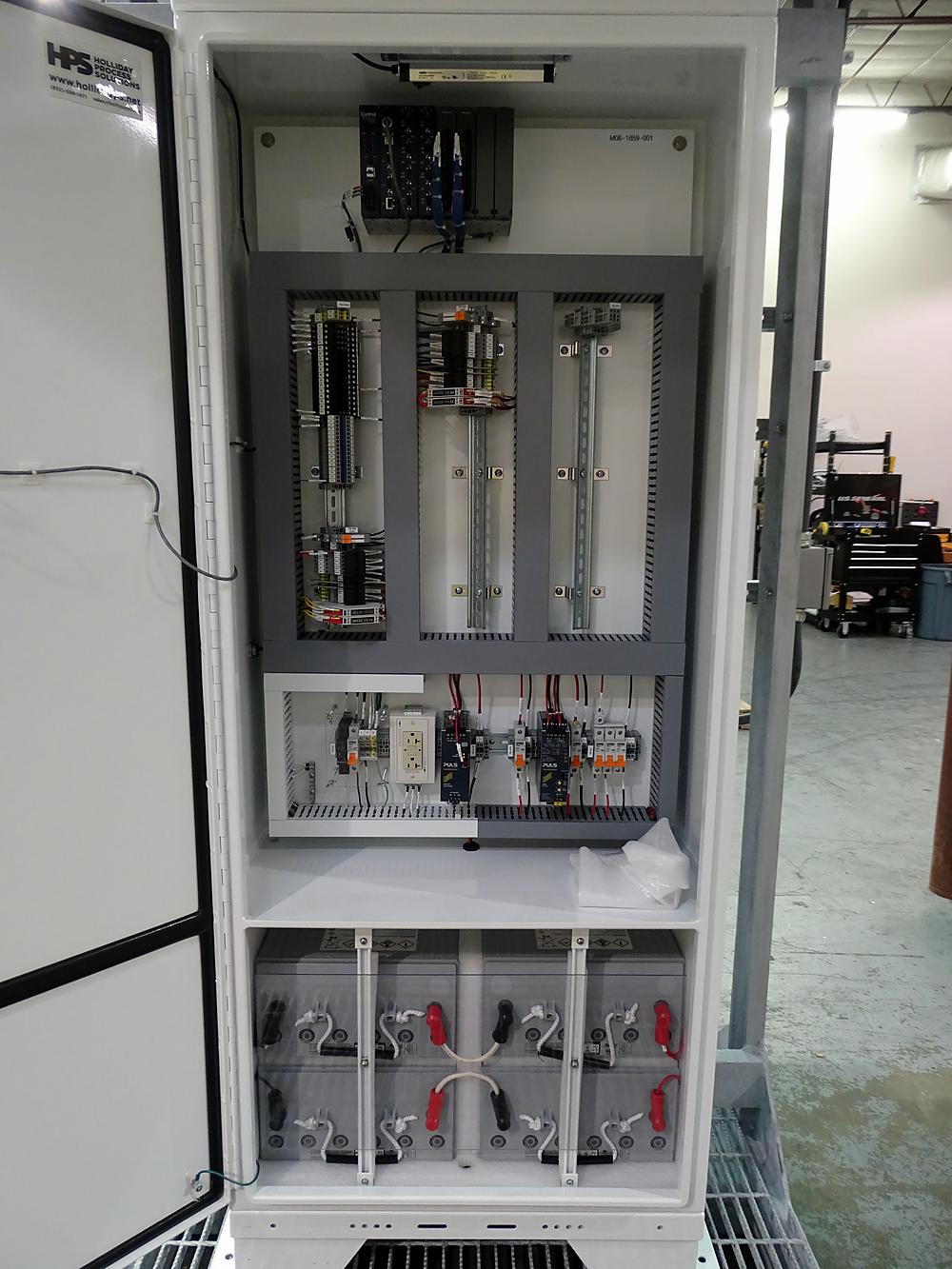
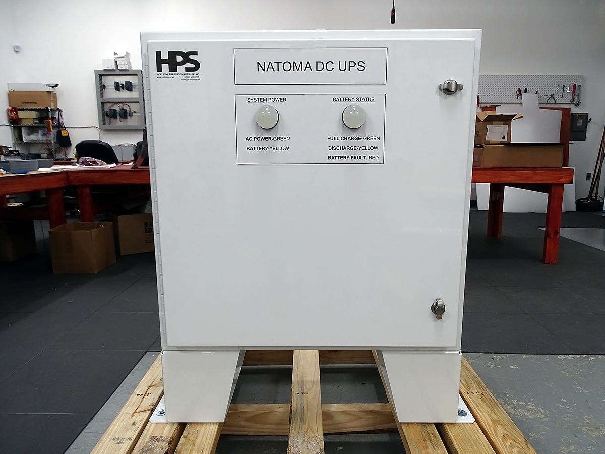
Our customers' equipment stays online through outages because it is protected from surges and because backup power keeps it running. A brief loss of power can cost millions; the UPS costs a fraction of that.
- 24 and 48 VDC UPS systems
- Battery cabinets and monitoring
- Status indication and alarms
- Integrated with the site's surge protection
The system your billing depends on.
Companies rely on flow measurement to bill their customers accurately, and on HPS to build systems that integrate with what is already on site. Every one ships with backup power and surge protection built in.
- Flow computer and RTU panels
- Transmitter and analyzer integration
- Custody-transfer grade wiring and documentation
- Protected and powered from day one
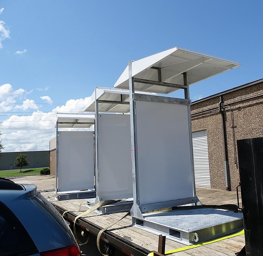
Designed with field personnel and geography in mind.
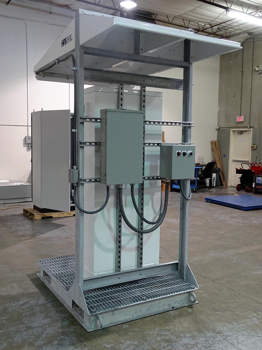
Skid-mounted, plug-and-play shelters and racks for remote or temporary installations. Set it, connect it, energize it.
- Skid-mounted shelters and sun shields
- Free-standing switch racks
- Pre-wired and tested before delivery
- Built for the climate it is going to
Radio, cellular and satellite, in one panel.
Telecom integration panels that have delivered across pipeline programs: router, radio or modem, DC power and protection, pre-configured and labeled for a one-visit install.
- Cellular, satellite and radio integration
- DC power and lightning protection
- Rack and wall-mount formats
- Coordinated with NexxtGen field crews
Keep the enclosure. Replace what is inside.
Equipment that needs better integration with supporting systems does not always need replacing. We retrofit most equipment to fit and integrate with custom applications.
- New controls into existing enclosures
- Protection and power added to legacy panels
- Documented to the current standard
- Minimal site outage
Describe the site.
Tell us what is there, what fails, and what the standard says. We will tell you which of these it is.